
The radio-transmission protocol is described fairly well in Tim’s thesis pg. 166-168.
Some important points to remmember and references:
Each 32-bytes radio packet contains, in order of low to high byte:
- 6 samples from 4 channels of raw data (on any part of the signal chain selected by gtkclient).
-
8 bytes of template matching.
Each byte indicates whether there is a spike detected for both templates of a group of 4 channels - if each bit represents one template on one channel, then all 8 bits of the byte will be taken. However, we make the assumption that the two neurons represented by the two templates on the same channel cannot both fire at the same time, this then allows an encoding scheme to compress the matching byte into only 7bits. The most-significant bit in the first four template-matching bytes are then replaced by the bits of an
packet # in framenibble. This nibble ranges from 0-15, representing the position of the current packet within the 16-packets radio frame.The next four template-matching bytes has their most significant bit replaced by the bits of an
echonibble. Thisechonibble is extracted from the last command packet gtkclient sent to the headstage, and allows a sort of SEQ-ACK exchange to happen between the headstage and gtkclient, although this only allows to know when a packet might’ve been lost – there is no bandwidth or CPU cycles to resend a lost packet. However, the control packets can be resent easily. TheSync headstagein gtkclient is a good way of sending control packets to sync the headstage configurations to those in gtkclient.
There are a total of \(32 \frac{channels}{amplifier} \times 4 \frac{amps}{headstage} \times 2 \frac{matches}{channel}=256 \frac{matches}{headstage}\), meaning it takes 4 packets to transmit all template matches, accompanied by 24 samples of 4 channels.
ADC runs at 1Msps, each packet requires 6 samples, so each packet requires \(\frac{6 samples\times 32 channels/sample}{1Msps}=192\mu s\), and 4 packets requires \(768\mu s\) to transmit.
Firmware sets aside a buffer enough for two radio frames. Each radio frame contains 16 packets. The radio starts sending when a frame is full, while the signal-chain collates and saves new packet in the other frame. Therefore, each frame takes about 3.072 ms to send, which is less than the 4ms free-run PLL time. Time to transmit, change to receive, then back is 3.60ms. So,
\[\begin{align} outgoingBW &= 32 \frac{bytes}{packet}\times 8 \frac{bits}{byte} \times 16 \frac{packets}{transmission}\times 1 \frac{trans}{3.072ms} = 1.333 Mbps\\ incomingBW &= 32 \frac{bytes}{packet}\times 8 \frac{bits}{byte} \times 1 \frac{packet}{reception}\times 1 \frac{reception}{3.072ms} = 83.33kbps \end{align}\]Received packet are 4 (memory address, value) pairs. Each value is 32 bits. Memory address should be 32bits, but since their upper nibble is always 0xf, they are replaced with the 4 bits echo value. In the radio loop handling received packets, the echo value is extracted and saved, while the memory address is restored. The values from the packets are then written to the corresponding memory address.
Debugging Notes
If the firmware used on headstage allows for radio transmission (i.e. radio_loop implements the described protocol), there are several ways to debug and check the quality of transmission.
-
If the headstage’s firmware is compiled correctly, the bridge’s firmware is compiled correctly, gtkclient is compiled correctly, and multicast is allowed, yet there are not signals showing up in gtkclient, then there is something wrong with the radio code within the headstage’s firmware.
-
If the gtkclient is getting raw waveforms displayed, but the waveforms look suspicious: for example, we apply sinusoids signals but waveforms displayed aren’t very smooth, that may be caused by either errors in DSP or radio transmission code. We can eliminate the former possibility if after gtkclient instructs the headstage to change coefficients to induce oscillations (see IIR oscillator post) we do indeed see sinusoids of the same frequency on all transmitted channels.
-
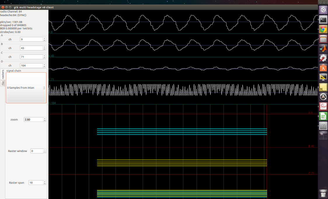
In gtkclient, if the
pkts/secfield is changing, but thedroppedandBERfields stays constantly 0, that means something is wrong with the radio packaging process. As great as 0 dropped packet sounds, it very unlikely.
I encountered these last two problems while finalizing the RHD-headstage firmware.
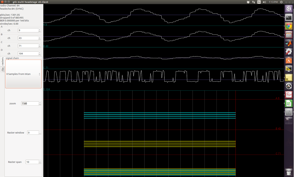
In the screenshots below, I applied square waves of known frequency to one of the amplifiers. The top three channels are floating, the fourth one is supposed to be the sinusoid applied. The firmware I used does not have any signal-chain steps so I was simply streaming the acquiared samples from Intan.
800Hz signal applied
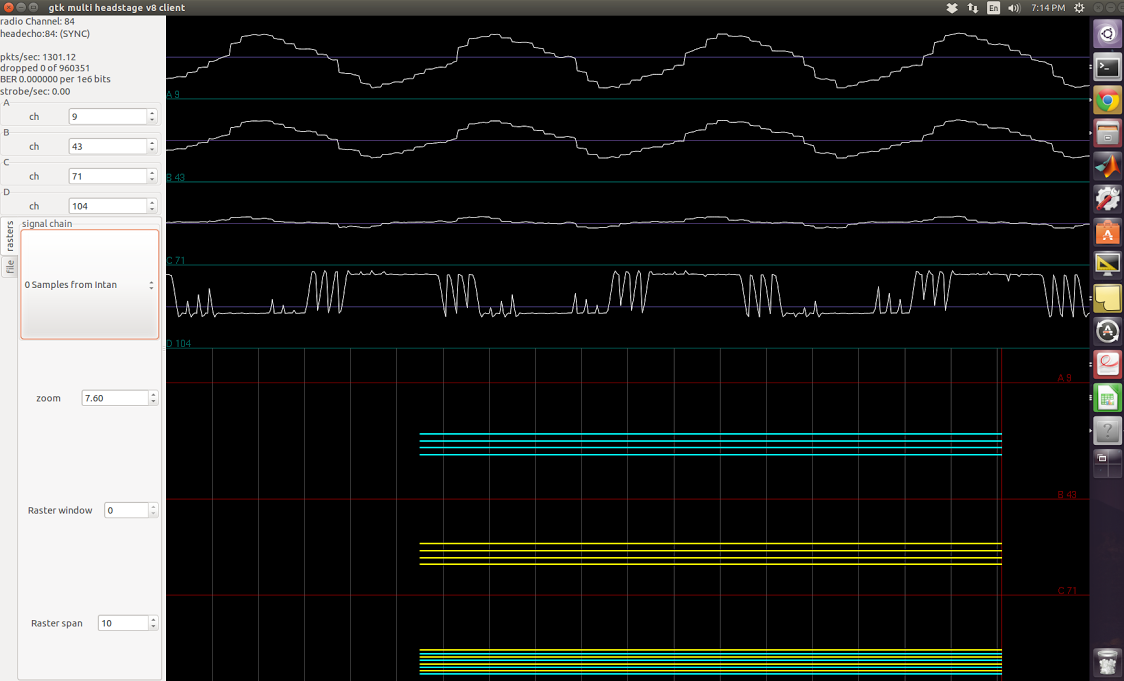
1kHz signal applied
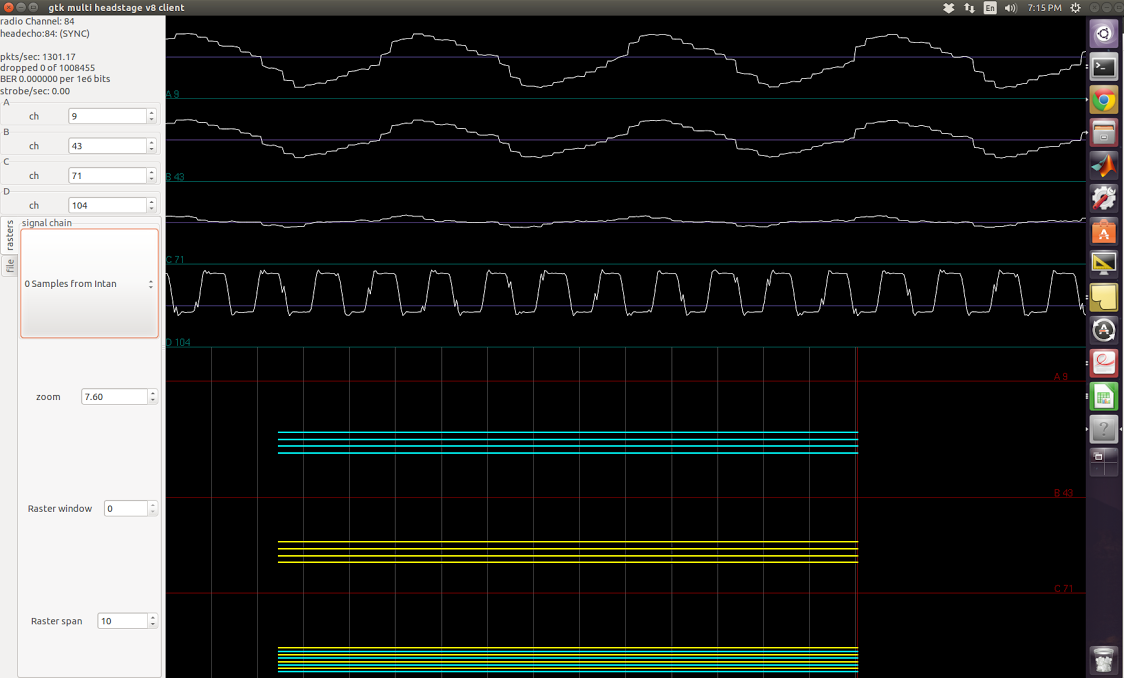
1.2kHz signal applied
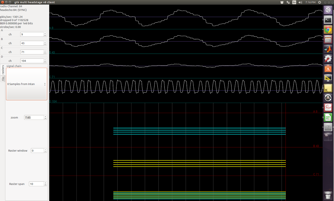
1.5kHz signal applied
2kHz signal applied
2.8kHz signal applied

It is apparent in most of these screenshots that I’m not getting a square wave back. In others, I get resemblance of square wave, but the frequency is never right, and the waveform seems to have multiple frequencies present, both higher and lower than what I expect.
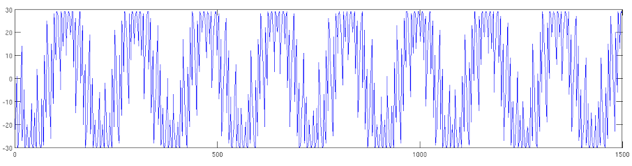
Transmitting the IIR-generated oscillations also showed distortions. The generated waveform is supposed to be 919Hz. The recorded signals, when dumped and plotted in Matabl is shown below:
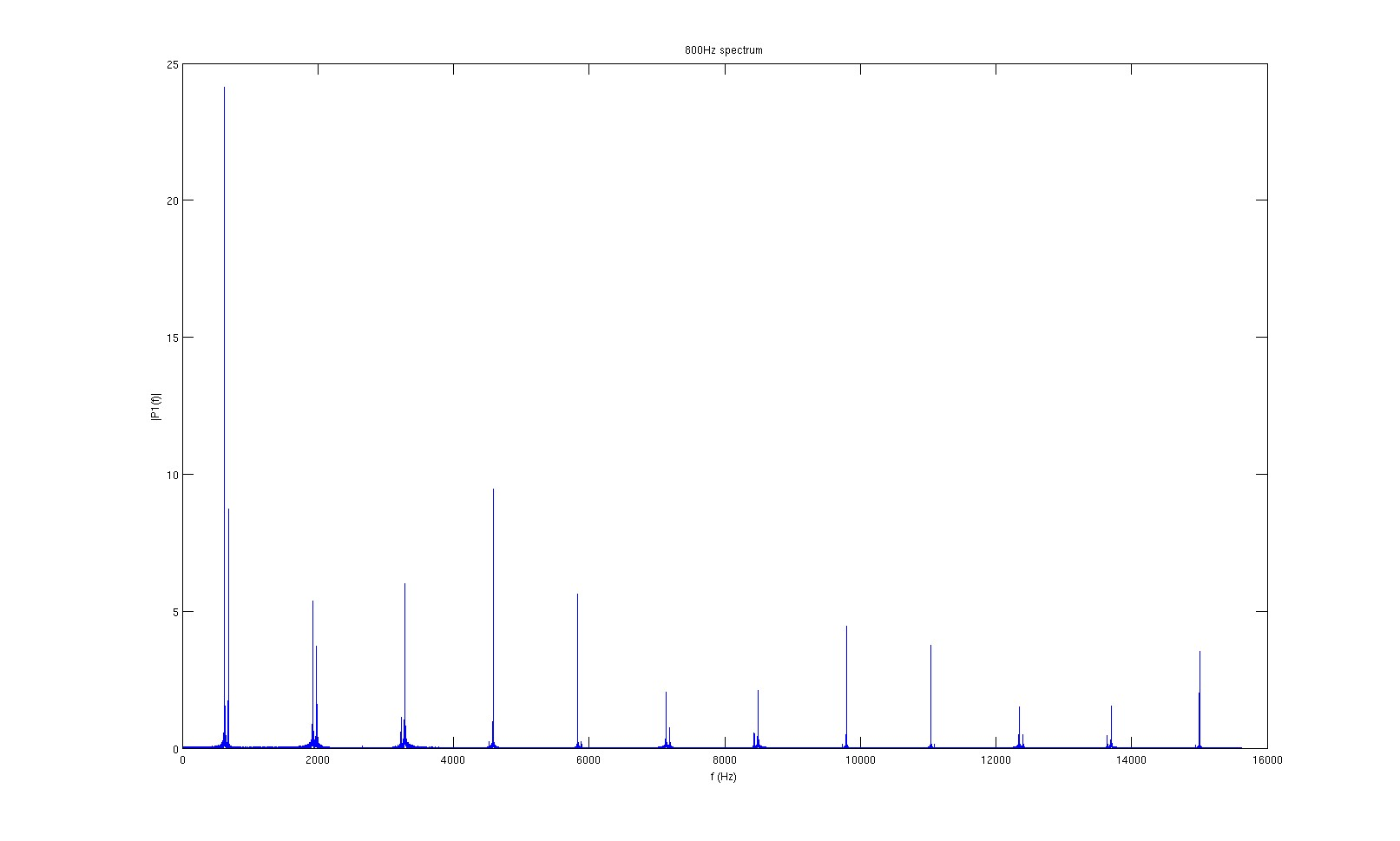
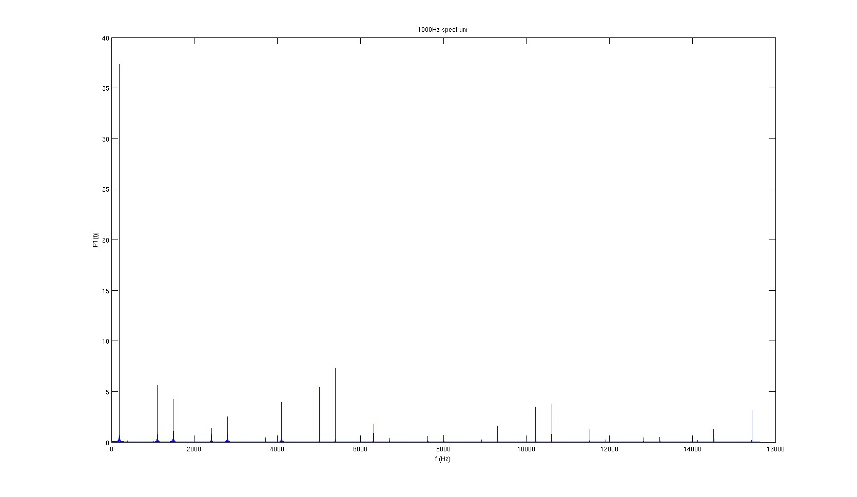
The first idea that came to mind to investigate what’s going on was performing FFT. Below are FFT of gtkclient recording when sinusoidal signals of different frequency was applied, as well as that of the IIR-generated oscillations.
800Hz signal FFT
1kHz signal FFT
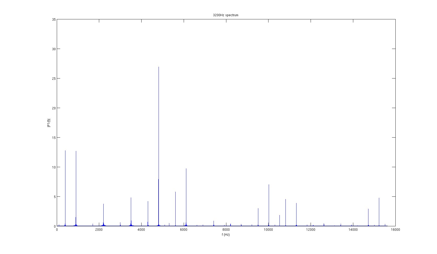
3.2kHz signal FFT
5kHz signal FFT
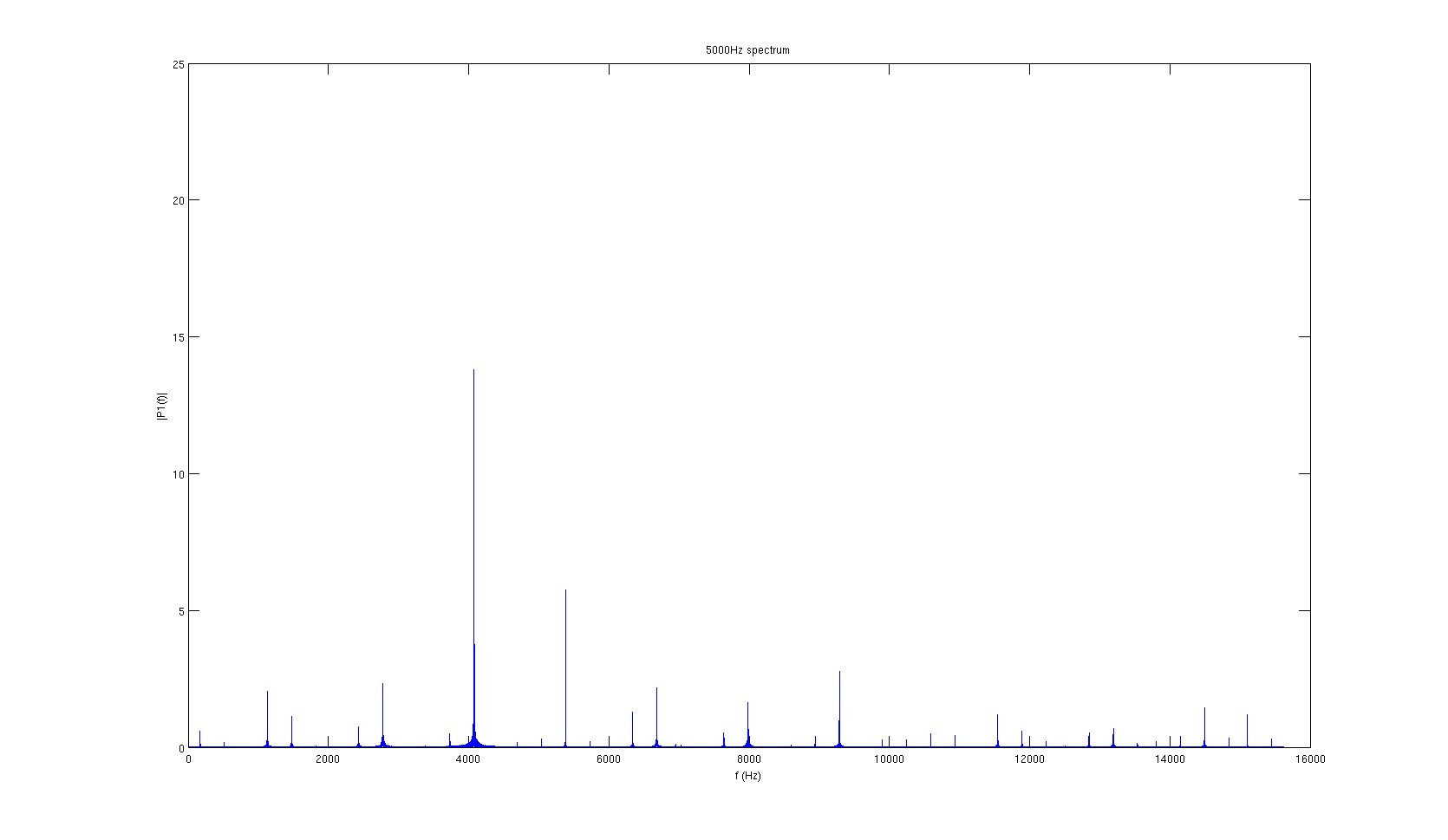
None of the spectra look very clean, and the signal’s actual frequency never has the most energy. However, it seemed that the highest peaks are consistently 1300Hz apart. Since the sampling frequency of the amplifiers is 31.25kHz, 1300Hz correspond to every 24 samples, or every 4 packets.
In the radio-transmission protocol, the spike-match bits are looped every 4 packets – the spike match bits rae saved in a buffer, and for every packet a pointer reads through this buffer. The pointer loops should therefore loop around the buffer every 4 packets, since all spike-match bits are transfered in that time.
Very careful line-by-line inspection of the radio packet assembly/transmission code revealed that I made a mistake modifying the original transmission code when modifying to work with firmware versions that did not include SAA template-matching. Fixing those errors solved the problem in all non-final RHD firmware versions.
That would mean after adding SAA, I only needed to copy over the original radio packet assembly/transmission code from RHA-headstage’s radio5.asm to get everything work. But it didn’t, and the same 1300Hz problem appeared. This then led me to a typo in my initial memory-allocation code in radio_bidi_asm, executed even before any of the signal-chain or radio-loop threads.
More Resources
Tim has notes on his radio protocol hardware/software development on his website, good read in case of any future Nordic radio work.