
The signal chain ends after IIR, at which spike matching happens.
Spike Templates
Spike templates are generated through spike sorting on gtkclient, then transmitted to and saved by the headstage. Spike sorting through PCA is described very well in Tim’s thesis:
Spike sorting on the client is very similar to that used by Plexon Inc’s SortClient and OfflineSorter: raw traces are thresholded, waveforms are extracted around the threshold, and a PCA projection is computed of these waveform snippets. Unlike Plexon, threshold crossing can be moved in both time and voltage domains, which permits considerably greater flexibility when centering a waveform within the relatively narrow 16-sample template region. […] PCA projected waveforms are selected by the user via a polygonal lasso, and the mean and L1 norm of this sample is computed. The former is sent to the transceiver as the template, and the latter sets a guess at the aperture. Aperture can later be updated manually by the user; as the aperture is changed, the GUI updates the color labels of the PCA projected points.
Image below shows spike-sorting in action:
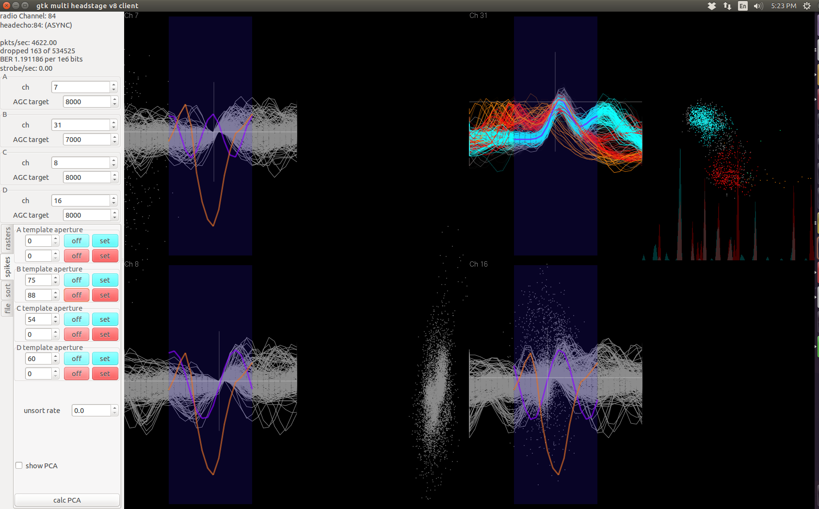
Note that this PCA template process can apply to any signal shape, not just limited to a neural signal waveform. In the screenshot, channel 31 is just noise when projected into the PCA space vaguely forms two clusters. The overlaid waveforms (cyan and red) don’t resemble any neural signal. But the fact that they overlaid simply tells us that the noise detected on channel 31 is not purely stochastic and probably contains interference from deterministic sources.
The 16-point templates in the time domain is limited only to the purple strip in the waveform window. For each channel, a maximum of two set of 16-point templates (16 8-bit numbers) can be stored on the headstage. For each template, the corresponding aperture is also stored as a 8-bit number.
Blackfin Implementation
The assembly implementation of template matching on blackfin (without LMS) is as below:
1
2
3
4
5
6
7
8
9
10
11
12
13
14
15
16
17
18
19
20
21
22
23
24
25
26
27
28
29
30
31
32
33
34
35
36
37
38
39
40
41
42
// At end of signal chain for both group of two samples
// Template comparison, plexon style. Sliding window, no threshold.
   // r2=samples from amp1 and amp2; r3=samples from amp3 and amp4. Pack them
   r2 = r2 >>> 8 (v);   // vector shift 16-bit to 8 bits, preserve sign
   r3 = r3 >>> 8 (v);
   r4 = bytepack(r2, r3); // amp4,3,2,1 (hi to low byte)
   r0 = [FP - FP_8080];   // r0=0x80808080;
   r4 = r4 ^ r0;          // convert to unsigned offset binary. SAA works on unsigned numbers.
   r0 = r4;               // save a copy for later

.align 8;   // template A: load order is t, t-15, t-14,...t-1
    a0 = a1 = 0 || r2 = [i0++]; //r2=template_A(t), r0 and r4 contains byte-packed samples just collected
    saa( r1:0, r3:2 ) || r0 = [i3++] || r2 = [i0++]; //r2=template_A(t-15), r0=bytepack(t-15)
    saa( r1:0, r3:2 ) || r0 = [i3++] || r2 = [i0++]; //r2=template_A(t-14), r0=bytepack(t-14)
    saa( r1:0, r3:2 ) || r0 = [i3++] || r2 = [i0++]; //r2=template_A(t-13), r0=bytepack(t-13)
    saa( r1:0, r3:2 ) || r0 = [i3++] || r2 = [i0++]; //r2=template_A(t-12), r0=bytepack(t-12)
    saa( r1:0, r3:2 ) || r0 = [i3++] || r2 = [i0++]; //r2=template_A(t-11), r0=bytepack(t-11)
    saa( r1:0, r3:2 ) || r0 = [i3++] || r2 = [i0++]; //r2=template_A(t-10), r0=bytepack(t-10)
    saa( r1:0, r3:2 ) || r0 = [i3++] || r2 = [i0++]; //r2=template_A(t-9),  r0=bytepack(t-9)
    saa( r1:0, r3:2 ) || r0 = [i3++] || r2 = [i0++]; //r2=template_A(t-8),  r0=bytepack(t-8)
    saa( r1:0, r3:2 ) || r0 = [i3++] || r2 = [i0++]; //r2=template_A(t-7),  r0=bytepack(t-7)
    saa( r1:0, r3:2 ) || r0 = [i3++] || r2 = [i0++]; //r2=template_A(t-6),  r0=bytepack(t-6)
    saa( r1:0, r3:2 ) || r0 = [i3++] || r2 = [i0++]; //r2=template_A(t-5),  r0=bytepack(t-5)
    saa( r1:0, r3:2 ) || r0 = [i3++] || r2 = [i0++]; //r2=template_A(t-4),  r0=bytepack(t-4)
    saa( r1:0, r3:2 ) || r0 = [i3++] || r2 = [i0++]; //r2=template_A(t-3),  r0=bytepack(t-3)
    saa( r1:0, r3:2 ) || r0 = [i3++] || r2 = [i0++]; //r2=template_A(t-2),  r0=bytepack(t-2)
    saa( r1:0, r3:2 ) || r0 = [i3++] || r2 = [i0++]; //r2=template_A(t-2),  r0=bytepack(t-1)
    saa( r1:0, r3:2 ) || [i3++] = r4; // write bytepack(t), inc i3

    // saa results in a0.l, a0.h, a1.l, a1.h (amp4,3,2,1); compare to aperture
    // i0 @ Aperture[amp1A, amp2A]
    r0 = a0, r1 = a1 (fu) || r2 = [i0++] || i3 -= m3; // r2=aperture[amp1A,amp2A], i3@saved bytepack(t-15)
    // subtract and saturate - if the answer is negative-->spike!
    r0 = r0 -|- r2 (s) || r3 = [i0++]; // r0=[amp1A match, amp2A match], r3=aperture[amp3A,amp4A]
    r1 = r1 -|- r3 (s);                // r1=[amp3A match, amp4A match]
    // shift to bit 0, sign preserved
    r0 = r0 >>> 15 (v); // r0.h and r0.l will be 0xffff or 0x0000 (match or not)
    r1 = r1 >>> 15 (v);
    r0 = -r0 (v);       // now 0x0001 or 0x0000 (match or not)
    r1 = -r1 (v);       // save both for packing later
    r1 << = 1;
    r6 = r0 + r1;       // r6=[14 zeros][amp4A][amp2A][14 zeros][amp3A][amp1A]
In non-LMS versions of firmware, incrementing by m3 moves address up by 16 32-bit words. In LMS-verions of firmware, incrementing by m3 moves address up by 2 32-bit words.
As mentioned in the Blackfins-Intan post, Blackfin works efficiently with two 16-bit samples at once, therefore the signal-chain operates twice before reaching the template matching step, once for each two samples acquired in a SPORT cycle.
This efficiency is due to Blackfin’s dual-MAC architecture, which can also operate on 4 unsigned 8-bit samples at the same time (treating each byte as a separate number).
Template matching implemented here is simply subtracting the 16 template points from a channel’s current and 15 past samples, then comparing the sum of their absolute differences to the aperture value. If the sum is smaller, then we declare a spike has been detected.
Luckily, Blackfin has the SAA instruction, which accumulates four different sums of absolute difference between vectors of unsigned bytes. Therefore, at the end of the signal chain after all four samples acquired have been processed, they are packed into a 32-bit word by first converting each signed 16-bit sample to offset binary, then take the most significant byte (line 1-7). These bytepacked words are saved for the past 15 samples for each group of four channels in a circular buffer.
The template vectors from the headstage are also written into memory in the same bytepacked form. Thus template matching becomes 16 successive SAA instructions (line 11-27).
Line 31-38 does the comparison between the SAA result against the saved template, resulting in either 0 for no match, or 1 for a match.
Consequences of this method
This biggest upside of this spike matching method is its speed and simplicity of implementation. However, despite the simplicity, this is probably not the most optimal or correct method for spike detection because:
-
In most sorting algorithms (e.g. Plexon), the raw signal is first thresholded, then waveform snippets of usually 32 samples long are compared to a template to accept/reject, or to sort them into different units. The comparison metric, or aperture in our implementation, is usually the MSE or L2-norm. Our implementation uses 16-sample window and L1-norm, which presumably may have worse performance.
-
Because the spike-sorting is based on 16-bit samples truncated to 8-bit samples, the templates themselves have truncation noise. The onboard spike-matching also involves truncation of the samples. How this truncation noise can affect the sorting quality has not been rigorously studied. But I expect this to not contribute significantly to spike-detection performance hit (if at all).
Literature suggests that for isolating a fixed-pattern signal embedded in noise, the best solution might be matched filter, which Tim has done a preliminary study on.