
Continuing to add on to the RHD headstage’s signal chain, I have to cut down on the number of biquads used to implement the butterworth bandpass filters on the Blackfin. The original code uses four back-to-back biquads to implement 8-pole butterworth filter.
The reason for using butterworth filter is because of the maximal flat passband. The reason for using back-to-back biquads rather than a big-chain (i.e. naively implementing the transfer function) is because each biquad uses only one summer, maximizing efficiency on embedded systems.
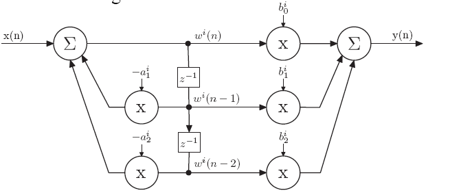
DF2-biquad
DF1-biquad
Most commonly, Direct Form II biquads are used in implementations because only 1 delay line is needed. However, as this great paper and [other common DSP resources] (https://www.amazon.com/Understanding-Digital-Signal-Processing-3rd/dp/0137027419) suggest, Direct Form II biquads have limitations on the coefficient range. Therefore, Direct Form I biquads are more desirable in 16-bit fixed-point applications for its better resistance to coefficient quantization and stability.
A lot of the original implementation rationale of the filters have been discussed in Tim’s post from a long time ago, it was decided that the filters would implement Butterworth type due to the excellent in-band performance. This post will mostly talk about how to generate the coefficients for the filters given the following assembly code structure per this paper again:
1
2
3
4
5
6
r5 = [i0++] || r1 = [i1++];  // r5=b0(LPF), r1=x0(n-1); i0@b1(LPF), i1@x0(n-2)
a0 = r0.l * r5.l, a1 = r0.h * r5.h || r6 = [i0++] || r2 = [i1++];    // r6=b1(LPF), r2=x0(n-2)
a0 += r1.l * r6.l, a1 += r1.h * r6.h || r7 = [i0++] || r3 = [i1++];  // r7=a0(LPF), r3=y1(n-1)
a0 += r2.l * r5.l, a1 += r2.h * r5.h || r5 = [i0++] || r4 = [i1++];  // r5=a1(LPF), r4=y1(n-2)
a0 += r3.l * r7.l, a1 += r3.h * r7.h || [i2++] = r0;                 // update x0(n-1), i2@x0(n-2)
r0.l = (a0 += r4.l * r5.l), r0.h = (a1 += r4.h * r5.h) (s2rnd) || [i2++] = r1; // r0=y1(n), save x0(n-2)
This code is the most efficient implementation of DF1-biquad on Blackfin. To implement new filters, we need to
- Get new filter transfer function.
- Factor the transfer function into biquad forms.
- Make biquad coefficients into correct fixed-point format.
Note that since we are only implementing filters that are cascades of biquads, that means any filters that we implement must contain an even number of poles.
There are two approaches for step 1 and 2. Approach 1 is easier for making filters low number of poles. Approach 2 is easier for high number of poles.
Approach 1
Since I only have enough code-path to implement two biquads (instead of four as Tim did), I need one LPF biquad and one HPF biquad. The filter can be designed by:
1
2
3
4
5
6
7
8
9
10
11
12
13
14
15
16
17
18
19
20
fs = 31250; % sampling frequency

% 2nd order butterworth LPF, cutoff at 9kHz
fc_LPF = 9000;
wn_LPF = (fc_LPF/fs)*2;  % normalized cutoff frequency (units=pi rad/sample)
[b_LPF, a_LPF] = butter(2, wn_LPF, 'low');  % descending powers of z, const firstA

% b_LPF = [0.3665, 0.7329, 0.3665]
% a_LPF = [1, 0.2804, 0.1855]

% 2nd order butterworth HPF, cutoff at 500Hz
fc_HPF = 500;
wn_HPF = (fc_HPF/fs)*2;
[b_HPF, a_HPF] = butter(2, wn_HPF, 'high');

% b_HPF = [0.9314, -1.8628, 0.9314]
% a_HPF = [1, -1.8580, 0.8675]

% plot freq-response of bandpass filter
fvtool(conv(b_LPF,b_HPF), conv(a_LPF, a_HPF));
The transfer function of a biquad is \(H(z)=\frac{Y}{X}=\frac{b_0+b_1z^{-1}+b_0z^{-2}}{1-a_0z^{-1}-a_1z^{-2}}\). However, the coefficients generated by the butter() function follows the form \(H(z)=\frac{Y}{X}=\frac{b(1)+b(2)z^{-1}+b(3)z^{-2}}{a(1)+a(2)z^{-1}+a(3)z^{-2}}\), so we need to reverse the sign of the last two values in a_LPF and b_LPF.
To make the generated coefficients into the actual values used on Blackfin, we need to be mindful of how many bits they should be. Since the result of the biquad (line 6 from the assembly snippet) uses the (s2rnd) flag, the result of the summer must be Q1.14 (so s2rnd result is Q1.15). This means all coefficients must be within Q1.14 (and hopefully can be represented as such):
1
2
3
4
5
6
7
b_LPF_DSP = round(b_LPF*2^14);    % result is [b0,b1,b0]
a_LPF_DSP = round(a_LPF*2^14)*-1; % result is [dont-care, a0, a1]
% b0=6004, b1=12008, a0=-4594, a1=-3039

b_HPF_DSP = round(b_HPF*2^14);
a_HPF_DSP = round(a_HPF*2^14)*-1;
% b0=15260, b1=-30519, a0=30442, a1=-14213
These resulting coefficients are what I ended up using in the firmware. The two code snippet above is in gtkclient_multi/genIIRfilters.m.
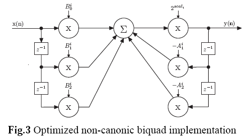
By multiplying the b-coefficients of the low-pass filter, we can increase the DC-gain without changing the shape of the gain curve (equivalent of increasing the in-band gain due to flatness of Butterworth). However, the resulting coefficients must be clamped within [-32768, 32767] so they can be properly stored within 16-bits.
This is desirable if the presence of high frequency noise makes the incoming signal envelope high and limits the gain, then LMS subtract this common noise. With the extra IIR-stage gain, we can amplify the signal in the passband more. It is not applicable to my version of headstage, because the raw samples are alreayd 16-bits. This is now implemented in gtkclient for all firmware versions with an IIR stage.
The total gain of each biquad is limited to the coefficient range in Q15. For LPF, the DC gain can be calculated as the sum of the filter’s feedforward coefficients divided by 1 minus the sum of the filter’s feedback coefficients (in decimal). Keeping the feedback coefficients, multiplying both feedforward coefficients by the same amount increases the DC gain of the LPF biquad by the same. In gtkclient code, we assumed static gain is 1, i.e. 1 minus the sum of the feedback coefficients is equal to the sum of feedforward coefficients. This is not entirely true, therefore, the IIR gain value represents how much extra gain the filter stage would provide over the base gain.
As the feedforward coefficient values have different magnitude, the same gain may saturate just one of the coefficients. In this case the gain scaling may change the filter’s shape. Therefore, in practice, the IIR gain entered should not be greater than [-2.5, 2.5]. To find the max IIR gain possible without saturating, find the smallest feedforward coefficient for the LPF biquad (m_lowpass_coeffs[0,1,4,5] for RHA or m_low_pass_coeffs[0,1] for RHD, in headstage.h, and divide 2 by that number).
Approach 2
The above approach is fine when we need one LPF biquad and one HPF biquad. But say we need an 8th-order buttworht bandpass filter, using the above approach we would need two HPF biquads and two LPF biquads. We can’t simply use two of the same HPF biquads and two of the same LPF biquads. The resulting bandpass filter will have less bandwidth between the -3dB points (two poles at same frequency means sharper roll-off from that point on).
The solution then, requires us to factor the generated transfer function (gtkclient_multi/genIIRfilters2.m):
1
2
3
4
5
6
7
8
9
10
11
12
13
14
15
16
17
18
19
20
21
22
23
24
25
26
27
28
29
30
31
32
33
34
35
36
37
38
39
40
41
42
43
44
% design butterworth filter, and derive coefficients for
% the cascade of two direct-form I biquads

fs = 31250;
% 8th order butterworth bandpass filter
% B and A in descending order of z
[B,A] = butter(4, [1000,9000]/(fs/2), 'bandpass');

% Factor the numerator and denominator.
% First get the roots of num and den: for roots
rB = roots(B);
rA = roots(A);

% get the polynomials for each biquad, each from two (conjugate) roots
% abs to take care of round-off errors - product of conjugate roots cannot be imaginary.
pB1 = abs(poly(rB(1:2)));    % num
pA1 = abs(poly(rA(1:2)));    % den

pB2 = abs(poly(rB(3:4)));
pA2 = abs(poly(rA(3:4)));

pB3 = abs(poly(rB(5:6)));
pA3 = abs(poly(rA(5:6)));

pB4 = abs(poly(rB(7:8)));
pA4 = abs(poly(rA(7:8)));

final_num = conv(conv(pB1,pB2),conv(pB3,pB4));
final_den = conv(conv(pA1,pA2),conv(pA3,pA4));
fvtool(final_num, final_den);   % plot resulting biquad cascade behavior

% convert to fixed point coefficients (Q1.14)
% b1(1) and a1(1) are the highest-order terms.
b1 = round(pB1*2^14);
a1 = round(pA1*2^14)*-1;

b2 = round(pB2*2^14);
a2 = round(pA2*2^14)*-1;

b3 = round(pB3*2^14);
a3 = round(pA3*2^14)*-1;

b4 = round(pB4*2^14);
a4 = round(pA4*2^14)*-1;
Ironically, the filtering behavior looks better for the 4th-order filter generated from Approach 1, shown below left is the 4th-order biquad cascades. Right is the 8th-order biquad (4 of them) cascades from Approach 2.
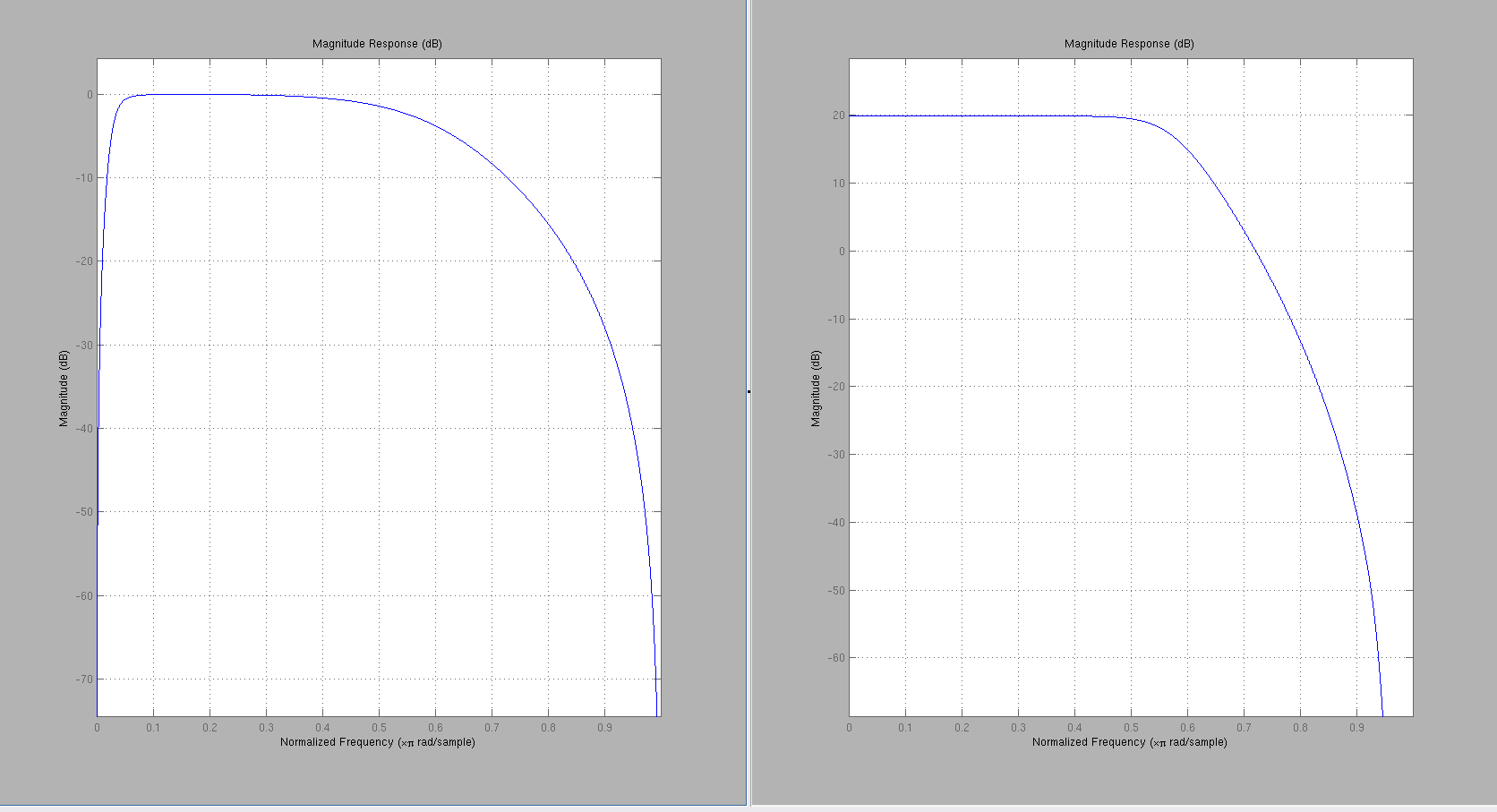
In the 8th-order filter, the HPF filter disappeared..not sure why?
Edit: 2/4/2016
Original bandwidth settings
- Intan cutoff freq: [250Hz, 10kHz]
- Intan DSPen setting: High pass above 300Hz
- Firmware AGC highpass: > 225Hz
- IIR setting: [500Hz, 9kHz]
- LPF:
b0=6004, b1=12008, a0=-4594, a1=-3039 - HPF:
b0=15260, b1=-30519, a0=30442, a1=-14213
- LPF:
Reduced bandwidth settings
- Intan cutoff freq: [250Hz, 7.5kHz]
- Intan DSPen setting: High pass above 300Hz
- Firmware AGC highpass: > 225Hz
- IIR setting: [500Hz, 7kHz]
- LPF:
b0=4041, b1=8081, a0=3139, a1=-2917 - HPF:
b0=15260, b1=-30519, a0=30442, a1=-14213
- LPF:
Edit: 4/6/2016
The new settings is:
- Intan cutoff freq: [1Hz, 10kHz]
- Intan DSPen setting: High pass above 1Hz
- Firmware
radio_AGC_IIR_SAA.asmAGC highpass: > 225Hz - Firmware
radio_gain_IIR_SAA.asm(final) AGC highpass: none - IIR setting: [250, 9kHz]
- LPF:
b0=6004, b1=12008, a0=-4594, a1=-3039 - HPF:
b0=15812, b1=-31624, a0=31604, a1=-15260
- LPF:
We widened the Intan’s hardware filter bandwidth so when sorting, the incoming waveform is less distorted and we can better see the spike features. The two stage IIR filters (2 poles on each side) are sufficient to attenuate the undesired out-of-band signals.
Edit: 7/26/2017
After implementing LMS, the input to IIR stage is much less noisy. Keeping the filter bandwidth setting the same – [250, 9kHz], IIR gain makes the spikes much easier to see. RHD headstages have comparable performance to RHA headstages, upon qualitative evaluation (heh).